Timer circuit

Learning objectives:

  • An introduction to putting together an electronic circuit
  • Understanding how a breadboard works
  • Practice putting together a circuit on a breadboard
  • Demonstrate how adjusting a resistor can change the frequency or amplitude of the blinking LED

How to use a breadboard:

Watch this video

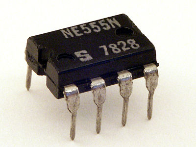
Parts used in the circuit:

This is the 555 timer microchip.
These are resistors. The colored bands are coded to show the resistance.
This is an electrolytic capacitor. Notice how the positive side has a longer wire.
This is a variable resistor. Turning the knob changes the resistance between the end wires and the middle wire.
This is a red LED. Notice that the positive side has a longer wire.

Constructing the 555 Timer Circuit:

Watch this video

The instructions we used:


Comments

Leave a comment