This is part of a series of posts on getting started with Arduino. Others in the series include:
- Arduino: Getting Started
- Arduino: Basic Troubleshooting
- Arduino: Understanding the Structure of C
- Arduino: Understanding Blink
This post focuses on learning to program the Arduino by modifying “Blink”, the first program that should be loaded to test your Arduino.
The Blink Program
void setup() {
  pinMode(LED_BUILTIN, OUTPUT);
}

void loop() {
  digitalWrite(LED_BUILTIN, HIGH);
  delay(1000);
  digitalWrite(LED_BUILTIN, LOW);
  delay(1000);
}
Modifying Programs
Writing a program from scratch can be difficult for a new programmer. The computer is very picky about spelling and punctuation and it can be a frustrating struggle to write a program that does anything without causing an error.
One of the best ways to learn to program and to demonstrate to yourself that you understand a program is to modify an existing program. This allows you to slowly make small changes to a working program and see if the program still works and works the way you expected.
Ways to Modify Blink
There are multiple ways that Blink can be modified. These ways are listed below in an order that generally goes from more simple to more complex. You can use the list to try to modify Blink yourself. This is the best way to learn. But, if you are stuck, I have covered the details of several of these modifications below.
- Have the LED stay on for 2 seconds instead of 1 second
- Have the LED stay on for 2 seconds, then go off, then back on for 1 second before repeating
- Control an external LED
- Control an LED from a different pin
- Have 2 LEDs blink at the same time
- Alternate the blinking of 2 LEDs
Changing the Duration of the Blink
In order to have the LED stay on for 2 seconds, the delay must be changed.
In the original code, there are two delay statements:
 digitalWrite(LED_BUILTIN, HIGH);
 delay(1000);
 digitalWrite(LED_BUILTIN, LOW);
 delay(1000);
The first delay determines how long the pin is held HIGH and the second delay determines how long the pin is held LOW.
Therefore, to change the duration that the LED stays on, you should change the first delay. The number refers to the number of milliseconds, so to keep the LED on for 2 seconds, the line of code should be changed to:
 digitalWrite(LED_BUILTIN, HIGH);
 delay(2000);
 digitalWrite(LED_BUILTIN, LOW);
 delay(1000);
Blinking for 2 Seconds Then for 1 Second
In this case, we want the Arduino to do two different things before repeating. Therefore, we can duplicate the code within the loop and modify one part of it to blink longer.
//on for 2 seconds
digitalWrite(LED_BUILTIN, HIGH);
 delay(2000);
 digitalWrite(LED_BUILTIN, LOW);
 delay(1000);

//on for 1 second
 digitalWrite(LED_BUILTIN, HIGH);
 delay(1000);
 digitalWrite(LED_BUILTIN, LOW);
 delay(1000);
Controlling an External LED
This is not a modification to the program. However, in order to be able to do anything more with an Arduino besides blinking its onboard LED, you will have to connect it to an external circuit.
The LED
This is an LED, which stands for light-emitting diode. There are two important things to know about an LED:
- Current can only run one direction through an LED, so it is important to connect the LED in the proper orientation. The long wire on the LED must be on the positive side and the short wire must be on the negative (or ground) side of the circuit.
- If you connect an LED directly to 5V (or more), there will be too much current running through the LED and it will quickly burn out. You must connect a resistor in series with the LED.

The Resistor
This is a resistor. It resists the flow of current through a circuit. There is no positive or negative end of a resistor. A resistor can be connected in a circuit in either direction.

The Breadboard
This is a breadboard. It is used to quickly connect parts of a circuit together.
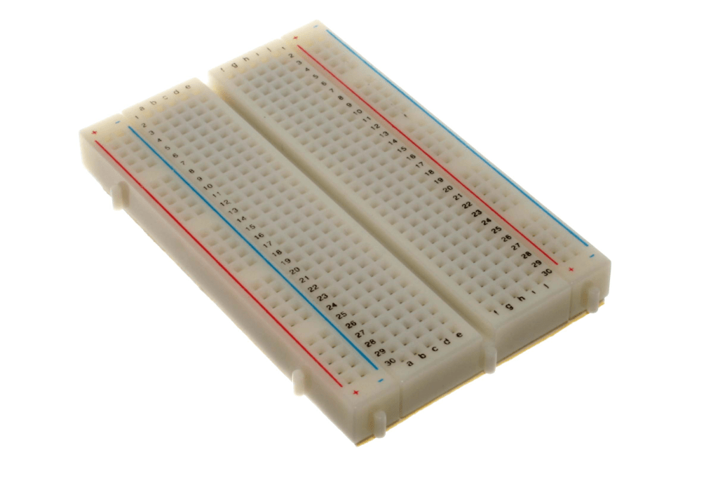
The green line segments on the breadboard below show which holes are connected together. Notice that each row of 5 holes is connected together. Also notice that the rows at the end are turned sideways and the holes are connected together along the entire length of the breadboard.

This is one way to connect the Arduino to an external LED using a breadboard.

Controlling an LED With a Different Pin
The key to this modification is to understand that LED_BUILTIN is a variable that is predefined by Arduino. For an Arduino UNO, LED_BUILTIN is equal to 13.
The original code could have been written like this:
void setup() {
  pinMode(13, OUTPUT);
}

void loop() {
  digitalWrite(13, HIGH);
  delay(1000);
  digitalWrite(13, LOW);
  delay(1000);
}
To control a different pin, you just need to change the pin number. For example, to control an LED connected to pin 12:
void setup() {
  pinMode(12, OUTPUT);
}

void loop() {
  digitalWrite(12, HIGH);
  delay(1000);
  digitalWrite(12, LOW);
  delay(1000);
}
Blinking Two LEDs Simultaneously
In this case, we combine the code we used to control the LED on pin 13 with the code for controlling the LED on pin 12. Almost everything is duplicated. But there is no need to duplicate the delays.
void setup() {
  pinMode(LED_BUILTIN, OUTPUT);
  pinMode(12, OUTPUT);
}

void loop() {
  digitalWrite(LED_BUILTIN, HIGH);
  digitalWrite(12, HIGH);
  delay(1000);
  digitalWrite(LED_BUILTIN, LOW);
  digitalWrite(12, LOW);
  delay(1000);
}
Alternate the Blinking
Here we want to turn one LED off at the same time that we turn the other one on.
void setup() {
  pinMode(LED_BUILTIN, OUTPUT);
  pinMode(12, OUTPUT);
}

void loop() {
  digitalWrite(LED_BUILTIN, HIGH);
  digitalWrite(12, LOW);
  delay(1000);
  digitalWrite(LED_BUILTIN, LOW);
  digitalWrite(12, HIGH);
  delay(1000);
}
Leave a comment