What is this?
What are the diagrams on the left?
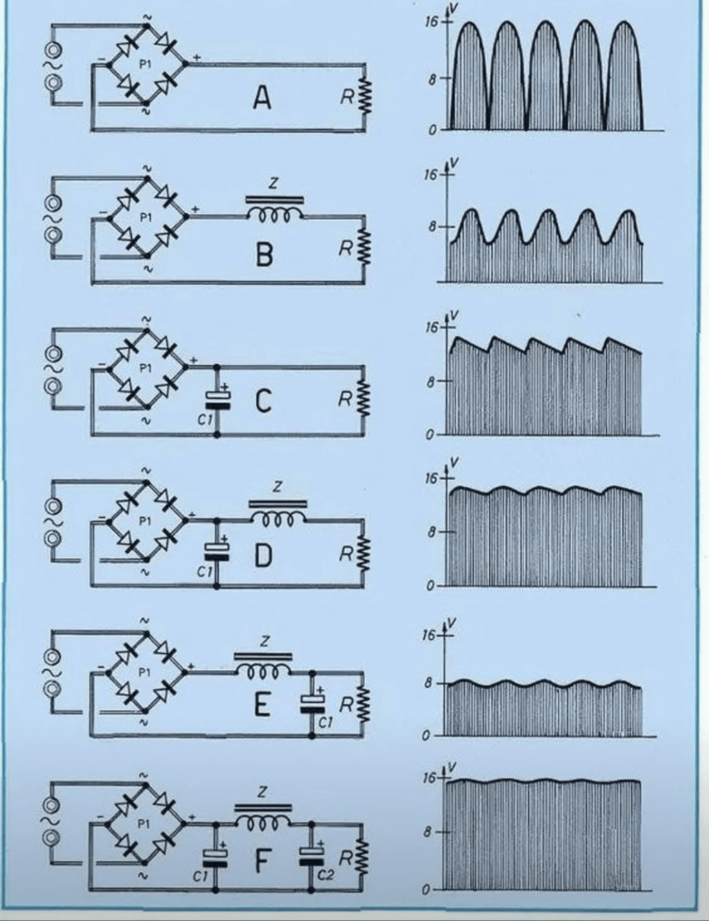
Circuit diagrams
What are the graphs on the right?
They are graphs of the electrical output across the resistor.
What does the V on the vertical axes represent?
Voltage
What do the horizontal axes represent?
Time
What do ~, +, and – represent around the square labeled P1?
~ indicates alternating current
+ indicates positive voltage due to a component of direct current
– indicates negative voltage due to a component of direct current
What electrical components are in circuit A?
There are three distinct components, from left to right. There is an AC power source. There are 4 diodes. There is one resistor.
What additional electrical component is added in circuit B?
An inductor
What additional electrical component is added in circuit C?
A capacitor
What does circuit A do to the alternating current powering the circuit?
It converts the negative half of the cycle of alternating current into positive voltage.
What does circuit B do to the alternating current powering the circuit?
Adding the inductor to the circuit reduces the circuit’s ability to change rapidly in response to voltage, so the maximum and minimum swings in voltage are reduced.
What does circuit C do to the alternating current powering the circuit?
Adding a capacitor to the circuit instead of the inductor also smooths out the changes in the voltage, but also has a higher average voltage.
What do circuits D, E, and F do to the alternating current powering the circuit?
Each subsequent modification of the circuit reduces the amount of variability in the voltage, getting progressively closer to the end goal of converting an AC current into a DC current.
Where might a circuit like this be found?
This circuit converts AC current (such as from a wall outlet) to DC current (often used by many electronic devices). A common example of a use for this circuit is in a phone charger.
Goals of this image:
- Pattern recognition
- Interpreting graphs
- Application of basic understanding of electricity

Leave a comment